
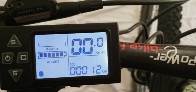
This LCD v2 manual brings together the archived document dated 01/08/2015, its P01–P08 settings and control illustrations. Use it to find a function or compare equipment with the original document. The technical tables are retained in full. Added explanations distinguish information specific to the historical installation from details the document does not establish.
Identify the LCD v2 manual and its display
LCD manual — version 2, document dated 01/08/2015.
The PDF states a version and date but gives no complete manufacturer model reference. Its display and button block are the available visual identifiers. King Meter is mentioned as a speed-signal source for P08; that does not identify the entire display as a particular model. This page therefore does not import settings from an LCD3, S866 or another similar-looking display.
Open the P01–P08 settings
Press and hold S− and S+ simultaneously. Use the same combination to save the settings and exit the menu. The display shows P01, followed by the other parameters in sequence through P08.
 +

| LCD | Settings |
|---|---|
| P01 | Set the outside tyre diameter to the nearest half-inch (0.5″). The readout is only as accurate as this rounding: a nominal 26″ or 28″ bicycle may have an actual diameter differing by 0.5″. Check the actual diameter. |
| P02 | Number of magnetic elements: 46 for the Power E-Bike rh205c motor. |
| P03 | Screen brightness: levels 1 to 3, increasing in brightness. |
| P04 | Choose the unit: Km or Mile. |
| P05 | Choose the voltage: 36 V, 46 V or 60 V. The value 46 V reproduces the original document. |
| P06 | Set the automatic switch-off time when the unit is not in use. |
| P07 | Speed setting in km/h or mph. |
| P08 | Hall speed-signal source: 0 for the King Meter Speed Sensor, or 2 for the Power E-Bike rh205c motor. |
Original-document annotation for P07: “100 = work at 100% capacity”.
Three points before changing a parameter
- P01: the document refers to outside tyre diameter, not simply the bicycle’s advertised wheel size. Rounding affects the displayed speed and distance.
- P02 and P08: the values 46 and 2 explicitly concern the rh205c motor mentioned in the document. They are not defaults for every motor.
- P05: the PDF really says 46 V. Keeping that entry is not a correction to 48 V or confirmation that every listed voltage suits the installed controller and battery.
For P07, the wording “speed kmh or mph” and the percentage annotation do not describe the same unit. The document does not fully explain their relationship. The value 100 is retained as an archive note, not an instruction to remove limits or reach a particular speed.
Use the buttons and distinguish annotations
The buttons distinguish between long and short presses, which have different functions.
| Button | Long press | Short press |
|---|---|---|
 Power |
Switch the screen on or off. | Change the multifunction display. |
 C |
Set the cruise speed. | Switch on the light and save an entry in the settings. |
S− |
No function is specified in the document. | Reduce the PAS level; decrease a setting value. |
S+ |
Change the speed display. | Increase the PAS level; increase a setting value. |
Annotation added to the original document: to switch off, make one long press followed by one short press.
These functions apply to the illustrated control block. The instruction to use a long press followed by a short press to switch off is an annotation, distinct from the main power-button description. No precise press duration or missing S− function has been invented. An archived cruise function does not establish the vehicle’s current conditions of use.
Identify wires in the documented installation
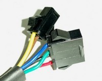
- Red: +.
- Black: −.
- White: send.
- Green: receive.
- Blue: switch.
- Yellow: light 6 V +.
- Brown: light 6 V −.
This list describes the illustrated harness; it is not a universal colour standard. The document does not provide a complete numbered pinout, the light output’s maximum current or all electrical levels on the send/receive wires. Before replacement, compare display and controller references and obtain the corresponding circuit information. Identical colours or connectors do not prove compatibility. Do not make powered trial connections.
Recognise display functions and fault symbols
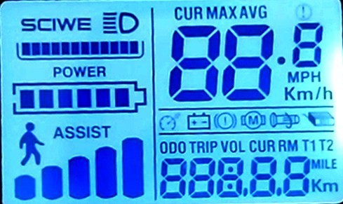
| LCD | Screen functions |
|---|---|
 |
Light on/off. |
 |
Current. |
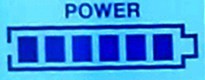 |
Battery voltage. |
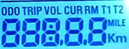 |
Multifunction odometer. |
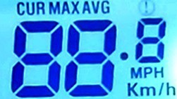 |
Average and maximum speed. |
 |
Failures and warnings. |
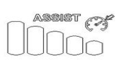 |
PAS level and cruise speed. |
 |
PAS assistance levels 1 to 5. |
Fault symbols
 Motor
 Throttle
 Controller
 Brake
 Low voltage
 PAS level and cruise speed.
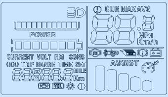
A symbol identifies a type of warning; it does not by itself prove which component has failed. Record the exact icon, associated display and circumstances before intervening. Battery voltage, current and PAS level describe different things. A battery gauge does not directly measure the riding distance remaining.
Check a setting without losing the original reference
- Compare the photograph, buttons and accessible equipment references with the document.
- Photograph every original value and note the displayed unit.
- Examine one documented parameter at a time and retain the other original values.
- Obtain the exact specification before changing an unidentified voltage, motor signal or connection.
- Use only the saving method described for this display; reopen the menu and record the saved value.
- If readings become inconsistent, compare with the original record rather than adopting settings for another model.
This keeps a usable point of reference. It supplies no undocumented factory reset or universal error-code table. The battery guide below explains the separate meanings of V, A, Ah and Wh.
Consult the original PDF manual
Both PDF pages were checked, including visible annotations and illustrations. The 46 V entry and percentage note for P07 are present. The exact commercial model and missing electrical ratings remain unestablished. No new hardware test is claimed.